DRAWING TO SOLIDWORKS

SOLIDWORKS models from drawings

Parts that exist only as 2D drawings,
rebuilt as editable SOLIDWORKS models with a feature history.

Home/Data conversion/SOLIDWORKS models from drawings

Long-running products, and parts designed before a company moved to 3D CAD, often exist only as 2D drawings. Every improvement, assembly check, prototype or spare-part order means someone reading the drawing and modelling it in 3D again.

We model those parts from the drawing as SOLIDWORKS models with sketches and features — extrudes, holes, fillets and so on. One drawing or a whole set, both are fine.

WHAT WE DO

What we take on

From DXF or PDF

2D CAD files such as DXF and DWG, or drawings as PDF. For scanned paper drawings and hand-drawn drawings, please ask us first: we look at whether they can be read. The model follows the dimensions on the drawing, and changes shape when you change a dimension.
From assembly drawings to assemblies

With part drawings and an assembly drawing, we model each part, put them together as a SOLIDWORKS assembly (.SLDASM) and check for interference.

Unclear points listed, not guessed

Missing dimensions, drawings that contradict each other, and illegible areas are not filled in by guesswork: we send you a list of questions.

In SOLIDWORKS 2024, 2025 or 2026 format

We send you SOLIDWORKS files (parts .SLDPRT, assemblies .SLDASM), saved for the version you use.

If you have STEP files, see STEP to SOLIDWORKS conversion.

EXAMPLE

Example

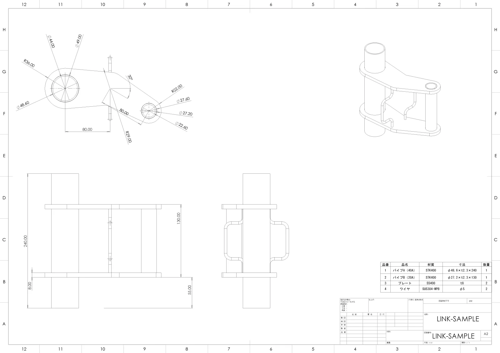
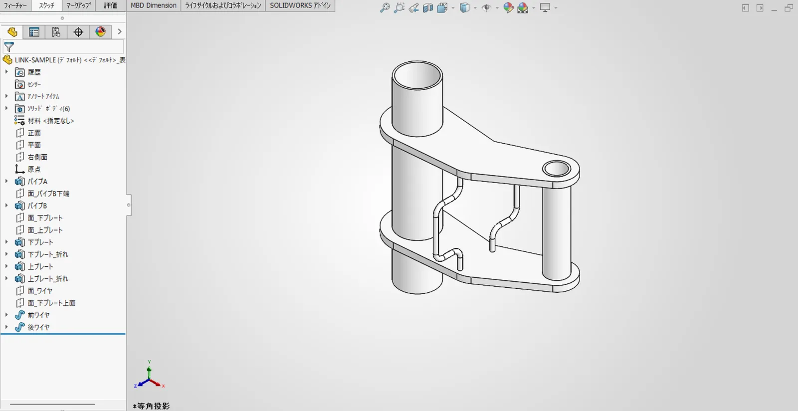
From a 2D drawing we build SOLIDWORKS data with a feature history for each member.

A2 2D drawing titled LINK-SAMPLE: orthographic and isometric views and parts list of a welded part made of two pipes of different sizes, two bent plates and two wires
Drawing: an A2 2D drawing. A part made of pipe (STK400 φ48.6 and φ27.2 t2.3), plate (SS400 t8) and wire (SUS304-WPB φ5), welded together.
The SOLIDWORKS model built from the drawing. The feature tree lists pipe A, pipe B, lower plate, upper plate, front wire and rear wire, with six solid bodies
After: the feature tree lists pipe A, pipe B, lower plate, upper plate, front wire and rear wire (labels in Japanese), with six solid bodies.

Click an image to see it larger.

HOW

Modelled by design engineers

Our mechanical design engineers model each part, comparing it with the drawing as they go. Mechanical structural design is our main business, so the people doing the work draw and read drawings every day.

HOW IT GOES

How it goes

1. Enquiry and NDA

Tell us the number of drawings, their form (DXF, PDF, paper…), whether they are parts or assemblies, and when you need them. We can sign a non-disclosure agreement before you send the production drawings.

2. Check the quality on a few drawings

We model a few parts first. You decide on the rest and the price after seeing the result.

3. Batch modelling and delivery

We model the rest and deliver each part as soon as it is finished.

The price is from $10 per item and depends on the shape. Quotes are free. For a quote, send non-confidential drawings through the quote request page (up to 100MB in total). For the full set of production drawings, we explain how to hand them over once the NDA is signed.

PRICE

Price

From $10 per item (excl. tax)

The price depends on the shape. Quotes are free.

* A handling fee applies per request (excl. tax): 1–9 items $100 / 10–19 items $50 / 20 items or more: none

Examples: 5 items = from $50 + handling fee $100 = from $150. 30 items = from $300 (no handling fee).

Tell us how many drawings, and in what form

Send non-confidential drawings through the quote request page. Quotes are free.

Request a quote